CMC Rogowski Current Probe
for measuring HF Common Mode Currents in VSDs and bearing spark erosion

 Powertek
 UK Tel: +44 1788 519911
 US Tel: +1 631 913 3242
 Email : info@powertekus.com
 Email : info@powertekuk.com

return to homepage | info@powertekuk.com | contact us


 CMC Datasheet pdf


Variable Frequency Drives (VSDs) used to control AC motors can produce large high frequency voltages that may appear on the machine shaft. These voltages are the result of capacitive coupling of the applied PWM voltage to the motor windings. The voltages on the shaft can be sufficient to cause a flow of arcing currents through the motor bearings to ground.

The discharging currents, or bearing spark erosion current, can cause heating and even melting of the surface of the bearing raceways. The damage caused by bearing currents can lead to premature failure of the motor drive as well as costly maintenance and down time.

Powertek has developed a flexible, clip-around, current probe to measure these high frequency common mode currents which flow through a motor to ground via the bearings in large AC drive systems. The probe is a modified version of our highly successful, industry leading, CWT range of Rogowski current sensors.

The CMC current probe is an important tool for identifying the presence and severity of bearing spark erosion currents and common mode currents in large motor drives. It is designed for use by experienced personnel with knowledge of AC drive systems. Once identified, the CMC probe will give an engineer a reference measurement which can be used to evaluate the effectiveness of steps taken to mitigate against bearing currents.

Product Features:

  • Coil length (circumference)
    500mm, 700mm, 1000mm - longer cables available on request

  • Coil cross-section (thickness)
    8.5mm max (14mm with removable silicone sleeve- only mechanical protection)

  • Cable length
    2.5m and 4m standard (connecting cable coil to integrator) - longer cables available on request

  • Battery options
    B-standard: 4 x AA 1.5V alkali batteries.  Lifetime typically 25hrs
    R-Rechargeable: 4 x AA 1.2V NiMH batteries.  Lifetime typically 10hrs.  External adaptor recharges batteries and powers unit.

  • Socket for external power adaptor (1.3mm diameter)
    (adaptor available as an option)

  • Output BNC Socket: Supplied with 0.5m BNC:BNC cable


 General Specifications
Peak Current 10A peak to 150A peak
Output ±7.5V peak
High Frequency Bandwidth (-3dB) up to 14MHz (CMC06 | 1000mm coil)
Low Frequency Bandwidth (-3dB) Varies with model type (refer to datasheet)
Accuracy (typ.) Calibrated to ±0.5% with conductor central in the Rogowski loop
Typical variation with conductor position ±0.3% of reading
DC Offset ±3mV maximum at 25°C
di/dt ratings Absolute max. 70kA/us (peak); 1.5kA/us (rms)
Operating temperature range 0°C to +40°C (integrator electronics)
-20°C to +90°C (coil and cable)
Coil lengths 500, 700 or 1000mm (custom lengths available)
Coil thickness 8.5mm max.
Peak coil insulation 10kV peak
Cable length (coil to integrator) 2.5 or 4m (custom lengths available)
Power supply Option 'B' Battery 4 x AA (1.5V standard alkali batteries)
plus - 2.1mm socket for 12V (±10%) DC input
Option 'R' Rechargeable Battery 4 x AA (1,2 NiMH batteries) with on-board trickle charge circuitry.
plus - 2.1mm socket for 12V (±10%) DC input
Output load ≥ 100.0 kohm (for rated accuracy)
Dimensions (H x W x D) 183mm x 93mm x 32mm
(7.2in x 3.6in x 1.2in)

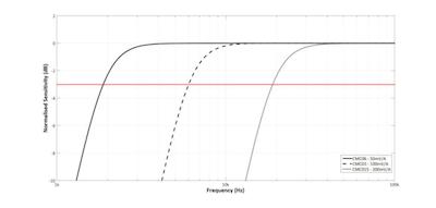
Low Frequency Characteristics
The low frequency bandwidth is set to attenuate any large fundamental frequency currents and magnetic fields. The CMC06 integrator has a gain of typically -90dB at 50Hz, this means that if there is a 100Arms, 50Hz current passing through the coil the output of the CMC will be <0.2mVrms.

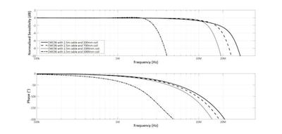
High Frequency Characteristics
The high frequency bandwidth of the CMC current probe is determined by the coil length, the cable length and the integrator design. The high frequency bandwidth for each model is quoted for a 2.5m cable and a 1000mm coil in the specification table.

Typical High Frequency Response (Model CMC06 -- 50mV/A)
Showing the variation of HF performance with coil length, 500mm coil up to 5000mm coil

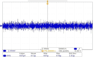
Noise Characteristics
The low noise integrator design allows better measurement accuracy of high frequency currents and enables a wide dynamic measurement range.

Typical noise – Model CMC03
Ch1 - CMC03/B/2.5/1000

Peak current range 75A, Sensitivity 100mV/A)
Time base 2ms/div

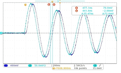
Delay Characteristics
The trace shows the CMC03 measuring a 2MHz sinusoidal current source compared with a traceable coaxial shunt measurement of the same current. There is a delay between the actual current and the output of the CMC which is predictable and is determined by the coil and cable length as well as the integrator design. The predicted delay for the CMC03B/2.5/1000 is 35ns.

2MHz damped sinusoidal current 16Apk
Ch1

- CMC03/B/2.5/1000 (Peak current 75A, Sens. 100mV/A)
Ch2
- Co-ax shunt 2GHz Timebase 200ns/div


CMC Current Probe Datasheet pdf


Return to Homepage