MC9010 Multifunction Calibrator for AC and DC Power and Energy, Resistance, Capacitance
MC9010 Multifunction Calibrator with 35 ppm basic accuracy
Multifunction Calibrator MC9010, a 35ppm precision calibration source suited to the needs of Calibration Laboratories - with options to store calibration data and sequences for each equipment type along with Win-Q-Base [data base], featuring voltage, current, power, energy along with thermocouple TC and RTD simulation
A precision 35 ppm AC/DC multifunction [multi-product] calibrator for certification of 6.5 digit multimeters, power analyzers, power meters and kWHr electric energy meters. The MC9010 Multi-product calibrator implements a modular design meaning it can be further customized to calibrate oscilloscopes, insulation testers, ac sources and transducers
Recertification of test equipment accuracy and function
Description
Multifunction Calibrator, MC9010, is a precision calibration source, with key features like voltage, current, power, energy along with thermocouple TC and RTD simulation. Multifunction calibrator MC9010 is designed as universal calibration tool for electrical calibration laboratories, covering most of their workload like multimeters, clamp meters, ohm meters, power meters and power analysers, energy meters, transducers, insulation testers, process meters, scopes and many others. High load capacity of voltage output (up to 50 mA) allows for calibration of high-consumption analogue meters. Installed harmonic and non-harmonic shape signals allow for testing meter sensitivity to distorted signals by a signal with various crest factor. Advancing from previous M14x calibrator series, 9010 can now calibrate even 400 MHz scopes, 1.5 kV insulation testers and 287 kW power meters. On the other hand we kept all the popular functions including complete transducer and external sensor calibration (strain gauge, pressure, torsion, force, etc.) using built-in multimeter, automatic uncertainty calculation, remote control and easy recalibration.

Basic Parameters
Basic function of the calibrator is the generation of calibrated DC/AC voltage in the range from 0µV to 1050V and DC/AC current in the range from 0 to 20.5A. Using a 50-turn coil the current range can be extended to 1025A. The best accuracy of the calibrator on DC voltage ranges is 35ppm, on AC voltage ranges 250ppm, on DC current ranges 130ppm and on AC current ranges 550ppm. Maximum frequency range is from 20Hz to 100kHz for harmonic output waveform. The calibrator is equipped with a function generator for periodic non-harmonic signals with defined crest factor, making it possible to test sensitivity of multimeters to distorted signals. In addition the calibrator simulates resistance and capacitance, the resistance range from 0.0 Ohm to 1100MOhm and capacitance from 1nF to 100µF can be simulated exceeding the required precision for calibration of common hand-held multimeters. Basic accuracies are resistance ranges 150ppm and capacitance ranges 0.1%.
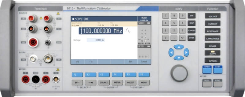
Frequency function of the calibrator makes it possible to generate a square wave signal with adjustable and calibrated duty ratio, frequency and amplitude in range from 1mV to 10V in the frequency band up to 10kHz. In the mode HF the square wave signal up to 20MHz with a very low rise-time can be generated. The frequency functions are suitable for the calibrations of corresponding frequency ranges of the multimeters and for calibration of the channel sensitivities and time bases of the oscilloscopes as well.
For calibrations of DC and one-phase AC power-meters and energy meters, the power – energy mode is determined. Output voltage can be set up to 240V and output current up to 20.5A with the power factor in range from -1 to +1 in the frequency band from 40Hz to 400Hz. Current capability of the voltage output is 30mA. It allows calibration of analogue power-meters which have higher current draw. For calibrations of the thermometers and temperature regulators, the function of simulation of temperature sensors is determined. Calibrator is able to simulate all common used Pt and Ni resistance sensors and TC sensors of the R, S, B, J, T, E, K and N types as well. Compensation of the TC cold junction is made either by entering value from the keyboard, or automatically by measuring the ambient temperature with Pt-100 sensor. The precision of the simulated resistance and TC sensors depends on set value and type of the sensor. For resistance sensors uncertainty band is in the range from 0.04°C to 0.5°C, for TC sensors from 0.4°C to 4.0°C.
Built-in multimeter
The MC9010 internal multimeter has a basic capability to measure DC current to 20mA, DC voltage to 10V, resistance to 2kOhm and frequency to 15kHz as standard. With accuracy of 100ppm it enables measurement of output signals of various types of transducers. With external TC or resistance temperature sensors, temperature can be scaled, as can external strain gauge sensors, for pressure, torsion, strength, etc. actual units can be measured and displayed.
Tester
Calibrator can be used in simultaneous mode, i.e. selected output signal is generated and the response of the device under test is measured at the same time by internal multimeter. Programmable capability of the calibrator enables setting of 10 steps defined by output signal function and output value on source side and awaiting response of DUT measured by internal multimeter including allowed limits of the DUT. The testing can run automatically.
Ease of use
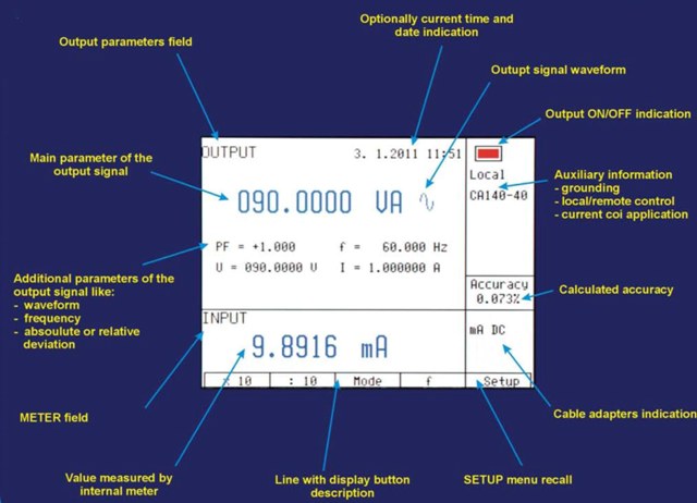
MC9010 Calibrator is equipped with a number of other functions which make its use easier. Among them belong possibility to set relative deviations from the actual value of the selected output signal, displaying of the output signal uncertainty, internal calibration procedure and others. Concept of the calibrator's control and indication uses a large area luminescence display on which all necessary information is concentrated. The control is perform by selection from the menu. Moreover, frequently used functions have firmly assigned keys with direct control. Normally, the calibrator is equipped with GPIB bus (IEEE-488), LAN, USB and an RS-232 serial port making it possible to be controlled by personal computer.
The calibrator can be included into POWERTEK WinQbase/CALIBER software calibration systems.
MC9010 calibrator is derived from previous successful models MC140/MC142. Compared to MC140/MC142 models the new MC9010 offers extended ranges and higher accuracy.
MC9010 Calibrator Data
Specifications
DC/AC voltage sine output
| Voltage Range: | 0 to 1040V |
| Frequency range: | 15Hz to 300kHz |
| range | % of value + µV | % of value + µV | % of value + µV | % of value + µV | % of value + µV |
|---|---|---|---|---|---|
| DC | 15Hz - 10kHz | 10kHz - 30kHz | 30kHz - 100kHz | 100kHz - 300kHz | |
| 0mV - 20mV | 0.022 + 3 | 0.2 + 30 | 0.2 + 40 | 1 + 100 | 5 + 900 |
| 20mV - 200mV | 0.0045 + 8 | 0.1 + 80 | 0.15 + 120 | 0.3 + 300 | 0.5 + 1m |
| 200mV - 2V | 0.0035 + 10 | 0.025 + 120 | 0.05 + 300 | 0.2 + 1m | 0.5 + 1m |
| 2V - 20V | 0.0035 + 40 | 0.025 + 700 | 0.05 + 1.5m | 0.2 + 10m | -- |
| 20V - 100V | 0.0042 + 250 | 0.027 + 5m | 0.05 + 15m | -- | -- |
| 100V - 280V | 0.0042 + 500 | 0.03 + 12m | 0.05 + 50m | -- | -- |
| 280V - 1050V | 0.005 + 7m | 0.042 + 85m | -- | -- | -- |
DC/AC current sine output
| Current range: | 0 to 20.5A |
| Frequency range: | DC, 15Hz to 10kHz |
| range | % of value + µA | % of value + µA | % of value + µA | % of value + µA |
|---|---|---|---|---|
| DC | 15Hz - 1kHz | 1kHz - 5kHz | 5kHz - 10kHz | |
| 0µA - 200µA | 0.05 + 20n | 0.15 + 150n | 0.30 + 200n | 0.5 + 500n |
| 200µA - 2mA | 0.028 + 100n | 0.085 + 300n | 0.20 + 1 | 0.50 + 1.4 |
| 2mA - 20mA | 0.015 + 600n | 0.05 + 2 | 0.2 + 10 | 0.5 + 14 |
| 20mA - 200mA | 0.015 + 6 | 0.05 + 20 | 0.2 + 100 | 0.5 + 140 |
| 200mA - 2A | 0.02 + 130 | 0.07 + 200 | 0.2 + 500 | -- |
| 2A - 20.5A | 0.025 + 2m | 0.1 + 6m | -- | -- |
**Maximal period for continuous current 20.5A is 30s. Maximal period for continuous current 20A is 60s.
Function Shape (non-harmonic signals)
Resistance and Capacitance
Function Frequency
| Voltage Range | % of value + µV |
|---|---|
| 1mV - 20mV | 0.2 +50 |
| 20mV - 200mV | 0.1 + 50 |
| 200mV - 2V | 0.1 |
| 2V - 10V | 0.1 |
HF mode (0.1 Hz to 20 MHz):
RTD temperature sensor simulation
| Type | °C | °C | °C | °C | °C | °C | °C |
|---|---|---|---|---|---|---|---|
| -200 - -190 | -190 - -100 | -100 - 0 | 0 - 250 | 250 - 460 | 460 - 630 | 630 - 800 | |
| Pt3850 Ro:100Ω | 0.05 | 0.06 | 0.07 | 0.09 | 0.12 | 0.14 | 0.18 |
| Pt3851 Ro:100Ω | 0.05 | 0.06 | 0.08 | 0.10 | 0.12 | 0.15 | 0.18 |
| Pt3926 Ro:100Ω | 0.06 | 0.06 | 0.08 | 0.10 | 0.12 | 0.15 | -- |
| Pt3916 Ro:100Ω | 0.06 | 0.06 | 0.08 | 0.10 | 0.12 | 0.15 | -- |
| Pt385 Ro:200Ω | 0.04 | 0.05 | 0.08 | 0.09 | 0.12 | 0.14 | -- |
| Pt385 Ro:500Ω | 0.04 | 0.04 | 0.05 | 0.08 | 0.12 | 0.15 | -- |
| Pt385 Ro:1000Ω | 0.03 | 0.04 | 0.05 | 0.09 | 0.11 | 0.14 | -- |
| Type | -80 - 0 | 0 - 100 | 100 - 260 | ||||
| Ni 120 | 0.05 | 0.08 | 0.14 |
TC Temperature Sensor Simulation
| R | range [°C] | -50 – 100 | 100 - 400 | 400 - 1000 | 1000 - 1767 |
| accuracy [°C] | 0.96 | 0.55 | 0.44 | 0.39 | |
| S | range [°C] | -50 - 100 | 100 - 250 | 250 - 1400 | 1400 - 1767 |
| accuracy [°C] | 0.9 | 0.56 | 0.49 | 0.40 | |
| B | range [°C] | 400 - 800 | 800 - 1000 | 1000 - 1500 | 1500 - 1820 |
| accuracy [°C] | 0.9 | 0.54 | 0.48 | 0.41 | |
| J | range [°C] | -210 - -100 | -100 - 150 | 150 - 700 | 700 - 1200 |
| accuracy [°C] | 0.3 | 0.25 | 0.21 | 0.18 | |
| T | range [°C] | -200 - -100 | -100 - 0 | 0 - 100 | 100 - 400 |
| accuracy [°C] | 0.3 | 0.26 | 0.21 | 0.18 | |
| E | range [°C] | -250 - -100 | -100 - 280 | 280 - 600 | 600 - 1000 |
| accuracy [°C] | 0.45 | 0.23 | 0.19 | 0.19 | |
| K | range [°C] | -200 - -100 | -100 - 480 | 480 - 1000 | 1000 - 1372 |
| accuracy [°C] | 0.35 | 0.25 | 0.23 | 0.24 | |
| N | range [°C] | -200 - -100 | -100 - 0 | 0 - 580 | 580 - 1300 |
| accuracy [°C] | 0.45 | 0.30 | 0.26 | 0.23 | |
| M | range [°C] | -50 - 50 | 50 - 100 | 100 - 470 | 470 - 1410 |
| accuracy [°C] | 0.25 | 0.22 | 0.21 | 0.20 | |
| C | range [°C] | 0 - 100 | 100 - 280 | 280 - 1370 | 1370 - 2315 |
| accuracy [°C] | 0.37 | 0.34 | 0.34 | 0.47 | |
| D | range [°C] | 0 - 100 | 100 - 280 | 280 - 1830 | 1830 - 2315 |
| accuracy [°C] | 0.45 | 0.37 | 0.34 | 0.47 | |
| G2 | range [°C] | 100 - 200 | 200 - 430 | 430 - 2080 | 2080 - 2315 |
| accuracy [°C] | 0.72 | 0.49 | 0.35 | 0.39 |
Built-in Process Multimeter
| Function | Range | Accuracy (%) | Resolution/Range |
|---|---|---|---|
| DC voltage | 12mV | 0.005 + 3µV | 0.01µV |
| 120mV | 0.005 + 5µV | 0.1µV | |
| 1.2V | 0.005 + 50µV | 1µV | |
| 12V | 0.005 + 500µV | 10µV | |
| DC current | 100µA | 0.02 + 20nA | 1nA |
| 1mA | 0.02 + 100nA | 10nA | |
| 2.4mA | 0.015 + 800nA | 100nA | |
| 24mA | 0.015 + 800nA | 100nA | |
| Resistance | 2kΩ | 0.02 + 10mΩ | 1mΩ |
| 20kΩ | 0.02 + 50mΩ | 10mΩ | |
| Frequency | 1Hz - 100kHz | 0.005 | 10µHz - 0.1Hz |
| TC Temperature | -250 - 2315°C | 0.2 - 1°C | TC Depends |
| RTD Temperature | -200 - 800°C | 0.08 - 0.42°C | Pt Depends |
General data
Accessories
Options (extra ordered)
| 0950 Current coil | Current coil 10x/25x/50x <1500A | Calibration of clamp ammeters |
| Adapter 9000-60 | for resistance and RTD measurement |  |
| Adapter 91 | Pt100 cold junction compensator |  |
| Cable 10 | Test cable 32A/1000V (black) | 1m length |
| Cable 11 | Test cable 32A/1000V (red) | 0.75m length |
| Cable 15 | Test cable 12A/600V (black) | 0.75m length |
| Cable 16 | Test cable 12A/600V (red) | 1m length |
| Cable 20 | Test cable BNC – BNC, 50Ω | 1m length |
| Cable 30 | Test cable BNC – banana, 50Ω | 1m length |
| Cable GPIB | GPIB cable | 2m length |
| Cable RS232 | male to female cable | 2m length |
| Option 90 | External Pt temperature sensor | Pt 1000 probe |
| GPIB to USB | GPIB to USB Converter | |
| RS232 to USB | RS232 to USB Converter | |
| WinQbase | Database application software | |
| CALIBER | Application SW for automated and semi automated calibrations. |
Contact Powertek today